GENERAL DESCRIPTION.
The author wished to design and construct a small 20 amp PSU that would give 13.8 volts DC for use with an HF transceiver. One of the most important considerations is that the PSU should have overvoltage protection set to trigger as close as possible to the output voltage. This will then ensure that in the event of a failure of the pass transistor, an unregulated output voltage will not be applied to the transceiver. Also, in the event of an overvoltage condition, the protection must clamp the PSU output instantly. This problem has been overcome by the use of a sensing IC, specially designed for overvoltage protection. Overcurrent protection is not required, as in the event of an excessive current demand, ie over 20 amps, the transformer will saturate and the voltage to the regulator will drop causing the supply to shut down.
There is much published material regarding the design of high current PSU's, however the designs are usually overly complicated and use many pass transistors and, in some cases, suspect over voltage protection circuits.
This supply has been designed and built by the author and duplicated by G3NBB. It has been used with the following100 watt HF transceivers, FT747, IC725, Atlas, and IC735 with complete success. Further more, with the exception of the case, all the components are available from RS Components, Farnell and Maplin. My minibox case was made by 'Retexbox', code: RM.13, and came from Tait in Glasgow, who are stockists of this range of cases. G3NBB obtained his case from a rally!
Returning to first principals, I decided to use a L723 voltage regulator, in a simple standard circuit implementation, with over voltage protection provided by a 3423 over voltage protector IC. The voltage regulator drives a TIP 31, (a TO220 device, no heatsink required) which in turn drives a single 2N6328 pass transistor, a 100 volt 30 amp TO3 device, mounted on a 75mm long, 11DN series IMI MARSTON heatsink. Thermal protection for the 2N6328 is provided by a 60mm x 60mm fan, switched by a tab mounted solid state 57C MOXIE thermal sensor mounted on the heatsink. Its tab is fixed directly to one of the pass transistor fixing bolts and is in contact with the heatsink immediatly behing the transistor. This ensures that the sensor tracks the case temperature of the transistor.
All the regulator and overvoltage circuits, including the TIP31 driver and fan sensing circuit, are contained on one small circuit board, mounted on the inside rear of the case. The size of the board is 100mm long x 25mm wide.
The transformer is an ILP 300VA 73014, 18v + 18v, 8.33 amps RMS toroidal unit, with the windings connected in parallel. The rectifier is a 50 volt 40 amp bridge. Over voltage protection is provided by the 3423 IC triggering a 40 amp thyristor, which shorts the PSU output to earth, blowing a 25 amp fuse. Please note, this fuse is only to disconnect the output from the smoothing capacitor, a 680000 micro farad computer grade device. This then discharges itself through a resistor which is permanently connected across it to earth. In the event of an over voltage condition the supply is clamped in less than 0.01 ms. The PSU output voltage is set at 13.8 volts and the trip voltage is set at 14.0 volts.
The 240 volt mains input to the PSU is through a 5 amp 12 volt relay, whose coil is energised by the 13.8 volt DC output of the PSU. To start the supply, the relay contacts are shorted by a momentary action push switch, and the 240 volt AC is supplied through a 10 watt 100 ohm series WW resistor. This provides a 'soft start' that allows the 13.8 volts PSU output to energise the relay coil, which then remains in this state until, either the mains is switched off, or the over voltage protection circuit triggers the Thyristor which clamps the 13.8 volt supply output to earth.
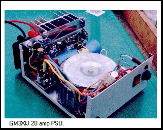
The supply is contained in a 155x75x175 minibox, with the fan and heatsink mounted externally on the back of the box. The fan blows air into the case which then discharges out of the case through the heatsink. The fan is designed to switch on when the heatsink temperature reaches 57C. During normal SSB operation at ambient room temperature, ie 20C, the fan only comes on when overs are long! Generally after about 10 minutes. In normal SSB break-in operation the fan rarely switches on.
To see photographs of the finished PSU please click on the links below.
If you would like further information on the PSU please E-M@il me.
Alternative AMATEUR RADIO TOPICS
To return to the SELECTION PAGE select this Icon 